Thursday, 26 February 2009

First look at an axle

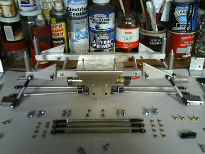
The first axle (front or back - it doesn't matter at this stage) has been offered up to the main chassis:


I've placed a pair of batteries into the chassis in order to assess their best location. The prime consideration here is to keep their combined center of gravity as low and as central as possible:


The outsides of the batteries contact the side link chassis mounts, and will require padding here. I've turned these screws around so that the fastener heads are situated inboard. These holes appear to double as tooling holes used in the pressing and punching of the lower chassis section, being as the are quite considerably oversize for their final use. The ESP instructions advise using a conical washer turned cone-to-plate to centralise these fixings in their locations. The anti-swaybar mounting sideplates co-located at this position, and previously acted as a doubler plate here, but because I'm not using them (yet?) I'm down to a single plate. I've actually tried using two cone washers here, one on each side of the plate, although the cones just contact centrally before the joint is actually closed. I'm going to give it a bit more thought here before I finalise the detail here, this area is relatively highly stressed and therefore prone to wear, especially the holes in the aluminium sideplates themselves.


The cantilever rod top mounts have been assembled as instructed. The cantilever rockerplate is M3 threaded for attachment, and the 16mm long screws show about five turns of protrusion beyond the plate. The flex in the bearing allows for contact and conflict between the end of the screw and the main chassis ladder rails:


On the opposite I've tried reversing the screw so that the head is inboard, this will tighter locate the screw in the plate. I might consider small right angled rub plates here, located at the convenient bodyshell mounts:


The lower central link axle mounts require drilling a new hole, identical to the existing one above the axle, to mount the rod to the 'C' plate:


The ball in the rod end is just at its extreme limit of travel here. This shouldn't pose a problem, but I'm going to look at spacing the mount just a little bit inboard to improve matters here. Whether or not this is going to affect motor clearance remains to be seen:


New Bits:

A stack of M3 washers @59p a pack. I've nearly used the first pack already!

A bag of M3 locknuts. 2p each or the whole bag of 100 for a quid. Guess which I chose!

A pair of servos. Cheapy chinese MG995s. £12.70 for two and £6.00 for postage and packing:

Tuesday, 24 February 2009

First Build


Most of the chassis is now lightly assembled. What I plan to do first is a 'mock up' build, basically to see how all the parts fit together, how much suspension travel is available, and how much clearance the major items have from each other at the extremes of articulation.

Most of the main linkages have been assembled, although one of the rods had a defective thread in one end, whereby the linking stud could be pushed home without rotation taking place! Presumably something went wrong in the production process, I'll have to think about sending it back, although I suppose it could be repaired, at least temporarily, with something like JB Weld.

I have deviated (as have others) very slightly from the instructions by placing the radio/esc plate underneath - instead of on top of - the main frame rails. I've done this it keep the center of gravity as low as I can. Currently my biggest consideration is going to be whether or not I can fit two standard batteries into the available space in the chassis. What I'm going to want is the longest possible run time I can reasonably achieve, say as close as possible to 30 minutes or so. It seems that 3800mah NI-MH packs seem to be the best buy for the money at the minute, so if I can fit two of these in I may achieve my requirement. What I also need is the ability to swap batteries easily whilst out and about with the truck, this is something I definitely have to think about whilst sorting the battery mounting final details.

As the kit comes, the battery mounts are fairly crude, being pressed sections that situate the battery 5/8" (16mm) above the bottom plate. Some of this space is needed to accomodate the lower main link mounting screw nuts (and washers being as I've added some here), whilst the sway bar kit also requires fitment here. As things stand, I've not fitted the sway bar kit because I'm going to lower the gearing to nine or ten motor gear teeth (from the stock thirteen tooth setup). The truck will be +/- 30% slower than it was before, to gain a proportionate amount of clambering and climbing 'grunt', and this will in some part negate the requirement for the sway bar. I've tried bending them by hand, and they certainly will help with restraining the natural body-rolling tendancies of a flat-out hard-cornering racer truck. How they may help or hinder the opposite requirements for medium-duty rock crawling activity is another question.

Sunday, 15 February 2009

Why the ESP kit?

When I set out to do this project I decided that I wanted to build a very adaptable and unique truck. I wanted something (A) that I could build and then modify over time to my own likely varying specific tastes, (B) could be used in a wide variety of outdoors environments, (C) would be very tough and would also withstand a fair bit of punishment, and (D) wouldn't overly break my own personal bank.

I didn't want to build a competition level crawler, and I didn't want to build a highly esoteric super speed truck that used only high-end components which would inevitably end up being a shelf queen for fear of crashing or otherwise damaging the damn thing.

In the end it came down to either building something from scratch, which would take a lot more time and effort (not to mention the possible difficulty of sourcing suitable materials), or buying a ready un-made kit. I looked at everything that is out there in the marketplace and eventually came down to a shortlist of three suitable contenders:

http://www.crawfordperformanceengineering.com/

The Crawford Performance Engineering Evolution. This kit comes in either 14 or 16 inch wheelbase versions and has the classic four link 'top and bottom link' layout. It sells for $159.99.

http://www.mnlart.com/Z-Crawler.html

The M&L Art budget chassis. This is very similar to the Crawford Evo chassis, you can choose between two sideplate designs, the one you see here and another one which features a skull and crossbones design. As shown here it sells for $124.00, although for another $60 you can have differential lockers, new gears, and 9 tooth pinions and the required adjustable motor mounts included.

http://www.esphobby.com/prod03.htm

The ESP Clodzilla IV. This is what I eventually chose over the other two. It cost me $139.99 direct from ESP via eBay, although it otherwise lists at $299.99. The kit does include a full set of steering linkages, mounts to place the steering servos above the gearboxes, a set of body mounts, and an anti-sway bar kit, not all of which are shown here.

What I liked about it were the long chassis rails which will make mounting the body very much easier, the four lower link set up, and the fact that ESP offer a lifetime guarantee on all their parts. The cantilever suspension is very interesting and allows for a great deal of adaptability, although at this stage of the project I am still not sure whether I will finally adopt this configuration as I think I may try out some of my own ideas involving a long laydown shock absorber configuration. I would not be the first person to adapt a 'Zilla IV by any means, here's one built by another owner (in the style of the Crawford and the M&L ), unfortunately I did not record his identity, but he gets top marks for his work.

Thursday, 12 February 2009

The ESP Clodzilla IV kit

As it arrives, the kit is contained is 7 polybags, each containing the parts for the different sub-assemblies of the chassis. Most of the smaller hardware is separately sealed into the same bags, and there is quite a lot of it.

Prior to unpacking:


Once unpacked:


By my count there are 386 individual items here. There are six instruction sheets, one for each of the assembly areas . Everything looks good so far, and it all appears to be here. First up, I'm going to assemble all the linkages, in order to reduce the spread of all the smaller bits...

Wednesday, 11 February 2009

Wow!!! That was quick!!

Earlier I wrote that I'd put the redundant donor Clod bits up on eBay to see if the they'd go. So I put the shell and the chassis into the auction this evening and guess what - they both sold for the full 'Buy It Now' price within 25 minutes! £17.99 for the shell and £19.99 for the chassis!! That's recovered almost exactly half the cost of the initial purchase price of the original Tamiya - making it a doubly definite bargain!

So it's out with the old and in with the new. Here's the new shell the last time it was in the company of the old one. It's lexan instead of ABS, was made for a Hoboa Monster Pirate nitro truck, and weighs in (complete with a flexible subframe) at 8.5oz (240 gm) as opposed to 1lb 5.5oz (575gm).


It came new, ready painted on the inside, with internal decals by Jackal (again from eBay) for £18.50. Also included was a sheet of external stickers for the windows and lights etc, the only snag was that the windscreen one said 'Monster Pirate' on the top of it, so a strip of ordinary black insulating tape has become a sunshield. Quite a good bargain I though to myself, being as similar unpainted shells, if you're looking for something specific, can easily fetch £45.

Welcome to my bench(s)!

OK - here we go. The stock Clod has been stripped and cleaned as far as necessary. It cost me £75 from eBay, and came with a two-channel Futaba set, a pair of S3003 servos, a 2400 mah battery, and a timed charger. "Hardly used and ready to go" the man wrote, and that seemed to be about right. Nothing was broken, and my girlfriend's kids had a happy hour ramming it into everything in the house. We didn't bother running it outdoors, being as the garden is very wet and muddy at this time of year (and added to the fact that the truck was reasonably clean to begin with).

Here's what I didn't need - the shell, the chassis and all the suspension - this will all end up back on eBay in the not-too-distant future in order to fund other parts for the project:


Here's most of what I'm keeping - the gearboxes, all the powertrain, the wheels and the tyres. I had thought about sourcing all this as new items (being as you can now get Clodbuster gearbox kits separately), but the costs far outweigh any advantages here.


I've set up the wheelbase at something like 14 inches (355mm) here, a tidy increase over the stock 10 5/8" (270mm). Also you can just about see that I've been experimenting with some long lay-down shocks - these are made for a HPI Savage XSS and are about 6" long. £8 for four, also off eBay (as is most everything I buy RC wise), new and full of oil.

Tuesday, 10 February 2009

Post #1

Hi - I'm Andy and I'm going to build a Clodzilla. I've had a go at building a couple of RC cars before, and I've had a go at writing a couple of blogs too, so this time I'm going to combine the two and see how we go!

I've bought myself a second-hand Tamiya Super Clodbuster and an new ESP Clodzilla IV Rock Crawler Conversion Kit. Both of these marques have been around for some time now, Tamiya have been producing pretty much unchanged Clods since 1987 (http://en.wikipedia.org/wiki/Clodbuster), and ESP (based in S.Wisconsin, USA, http://www.esphobby.com/) have been producing a range of aluminium RC conversion kits since 1990.

Anyway, I've got a few ideas of my own to throw into the mix. I expect the project will take six months or so, with time and funds for other bits and pieces allowing. All the parts I have are on the bench. Here we go... well tomorrow morning anyway!