Monday, 7 December 2009

Ram Truck


Not sure if this is a new project or a variation of an old one. I bought 1/16 scale New Bright Dodge Ram truck on eBay for 99p. These are £25 in the shops, and as they go are fairly pretty trucks. They run on 4x AAs, have rubbish steering and no suspension. One of my TL-01B/Baja King/Champ chassis has now got much bigger crawler type tyres mounted on cheapo 26mm wide touring wheels. They're very soft and squidgy and came with foam inserts to help maintain their shape. The New Bright shell will need drilling to fit straight on the existing mounts, but that's easy peasy. I've bought an integy 45 turn lathe motor for it, and I'm going to lock the rear differential and move the ball diff currently in the back to the front. It should be good in the woods!


Friday, 30 October 2009

Bigger and (hopefully) better pictures

I've worked out how to change the page width of these 'Blogger' pages by changing some of the settings in the template settings tab. The old page was set for a width of 660 pixels which meant the main content was limited to 410 pixels. I've changed this to 760px and the main content to 520px, this is the largest size page that will display properly in 800x600 resolution, and takes the content to (near) full screen width at this setting.

As far as the pictures are concerned, I had been loading them at 400x300 pixels as this was the best size for the display in the old width, whilst the originals were a bit too big for uploading directly. From now on I'll resize them so they display on a 800x600 screen. I'll do the same for the last few that I've posted as well.


Meantime the Clodzilla has had its cage painted black along with its mounts, I did this by hand using satin enamel being as this will be easy to touch-up when it gets scratched, and I've made some headlight mounts.

Blue-now-red and yellow truck, as seen in the bottom pic, has also received some nice new wheels and tyres. They're Colt M1168 5 spokes, and I'm sticking with F-350 tyres.

Saturday, 17 October 2009

'Zilla Rocks!


Anchor Head, Weston Super Mare, North Somerset, England. Good Rocks!

Saturday, 26 September 2009

Blue Truck gets a makeover

I found this bodyshell on eBay. I think it's a Proline Chevy Mini Rock Crawler shell, at least that was what the listing said, though I can't find another reference using this exact title in searching. I won and paid £1.24 for it undrilled and freshly painted as the second bidder, plus a fair bit (£6.99) for postage. It would seem a lot of eBayers are doing this to cover themselves pricewise whilst listing at a (lowest cost to themselves) 99p start price.


Since these photos were taken I've mounted the body properly using normal TL-01 touring car posts, and have made some little triangular plates to re-mount the bottoms of the shocks whilst giving me an extra bit of ground clearance. The aerial is now under the shell for a cleaner look, though this might need a bit of fiddling with as it seems to be causing a bit of glitching. This method worked fine on Sean's Army Truck, 'tho that was running a 27Mhz system and this is on 40Mhz with a (seemingly?) correspondingly longer aerial wire. No new motor yet - I did get one from the usual source, it was listed as a 'modified 45' but was actually a 19 turn triple wound MRI item. Oh well we'll see what I can afford come next pay-day!

UPDATE:

It's apparently a 1972 Chevy® C-10 body. They come in two sizes, for 1:10 and 1:18, both priced (unpainted) at £20.49 plus P+P on eBay.

Wednesday, 9 September 2009

Cage Shell V1

I quite like my lexan shell. I know it's going to get wrecked on the rocks. Besides which it doesn't allow for full suspension travel unless it's mounted higher than looks right. So I've made this:


It's just a piece of inch-and-a half squared plastic-coated mesh cut, bent and twisted to form the shape of a shell. It's just about the right size now - although it still needs a bit of tidying up. I might even add headlights...

Sunday, 30 August 2009

Meantime (II)...

Not much more has happened with the Clodzilla since I last posted here. I've done a bit of fine-tuning with the radio but it hasn't been outside yet. The main reason for this is that I was worried about the vulnerability of the front and rear steering cranks, being as they remains the stock plastic items. The truck itself certainly has some ooomph, and a crank is sure to get wiped out the first time it meets something hard. I've looked at the various bumper options, and to be honest I think the standard items are as good as anything else. They just have to be black though, so to this end I've ordered the relevant sprues from Japan, being as this is the only place I can get them from. The newer chrome edition Super Clodbuster has black bumpers, instead of the red, blue or yellow ones from the other models. They're here now so I can get going again. In the meantime I've built a couple more cars (well - a buggy and a truck) for my partner's kids to use. They've both had lesser RC vehicles before but now they're entering proper Tamiya territory! I had to get them for them otherwise I'm not going to get a look in myself with the 'Zilla. My go... My go... My go...

Kala's Rising Fighter:


Kala has just turned 8 and this one is for her - a new and completely standard Rising Fighter, although it's been sprayed a nice shade of pink (as was her wish) and has dinky red wheel nuts. The Rising Fighter is one of Tamiya's latest buggies, and uses a Grasshopper 2 chassis and running gear. It's a 'parts bin' special by all accounts, virtually eveything comes from one existing car or another. It goes quite well though and it's also very easy to drive. It surprised me with the good run-time we got out of one 1900mAh battery pack - the blue New Bright TL-01 truck (see below - 3 July post) just about killed two 2400mAh packs whilst running alongside and sometimes behind!

Sean's Army Truck:


'Twas Sean (nearly 10) who was driving the blue truck at the same time as Kala was getting used to her buggy - this might go some way to explaining the battery life, all that I can really say is that he is a bit more throttle happy although she is a better driver! For his truck it's another second-hand TL-01 chassis, this time from a standard 190mm car. I've given it longer Seben Racing (TL-01B clone) monster truck shocks and Tamiya Mitsubishi Pajero wheels and tyres. It's got a 540J motor against the blue truck's shiny Mabuchi RS, and it seems to be a fair bit torquier (if that's the right word/spelling? - it's not in my dictionary???). The Pajero tyres are also a lot harder than the F-350's, so it wheel spins a hell-of-a-lot more and does neat doughnuts. Indoors on a smooth wooden floor it manages a fairly good impression of being a drift car!

Anyway we'll see how long both of these cars last and how much abuse they can endure. I will keep you posted...

BTW - here are the figures for the two different motors just to prove the point (and also just in case you are interested in making a similar choice somewhere along the line):

RS-540J Johnson:

Torque at best efficiency: 255g-cm
R.P.M. at best efficiency: 14,500rpm (7.2V)
Current drain at best efficiency: 7.9A (7.2V)

RS-540SH Mabuchi:

Torque at best efficiency: 194g-cm
R.P.M. at best efficiency: 15,080 rpm (7.2V)
Current drain at best efficiency: 5.9A (7.2V)

Because of this, the blue truck may well be getting a new motor quite soon. The choice will probably be between a Tamiya "dirt tuned" 27 turn motor, part number #53929; or a Tamiya "lightly tuned" 28 turn motor, part number #59383.

The available figures for comparison are:

Dirt Tuned:

Number of turns = 27
Usable Voltage = 7.2
Torque at best efficiency = 380g/cm (7.2v)
RPM at best efficiency = 17,000rpm (7.2v)

Lightly Tuned:

Number of turns = 28
Usable Voltage = 7.2v
Torque at best efficiency = 564g/cm (7.2v)
RPM at best efficiency = 16,300rpm (7.2v)

Current drain for either motor is not quoted, although I expect it to be a fair bit higher than either of the two 'stock' motors.

Thursday, 30 July 2009

Up and running!


The Clodzilla is now a runner. Initial impressions are of a whole load of torque, although on the downside there is an equal whole load of flex in the steering assemblies. I know that ESP offer metal steering transfer joints to replace the stock plastic items, but these will not fix the not inconsiderable movement in their right angled servo mounts. I've mounted the fore and aft rods two holes higher on the servo bellcranks than the static range suggested, and this compensates for the flex to a degree, but this isn't the ultimate solution. The servo mounts pick up on the two standard motor mounts, unfortunately they would have been better if these items had been longer and had three mounting holes, possibly utilising the screw location on the very back ends of the gearboxes. I didn't cut off the standard servo mountings on the servos themselves so I may be able to make an additional brace using these.

As far as the radio set-up goes everything went fine. I've still got a bit of tinkering to do, particularly on the braking side because the truck stops a little too dead as soon as I take my finger off the trigger. I didn't need to reverse one of the channels as suggested below, and whereas someone on the forum (linked to below) had trouble getting his rear servo to work in both directions this was overcome by setting the CH3 value to zero where it had previously been set to 100, although I don't know what the default value was because I have a second-hand transmitter and I didn't reset it to the factory settings, instead I simply adjusted the values to those required.

There are still a few things to do, like touching up a couple of scratches and mounting the off/on switch. I've also got to remake the battery joining leads as I think I need a thicker cable at the paired end, I didn't have any 14 or ideally 12 AWG cable when I was making them, and anyway it was a trial run to get the lengths right. I've spurred off an extra pair of leads from the point where they join together to create a remote charging point because all the other joints are a bit inaccessable.

The truck now weighs in at just under 10lbs, discounting the shell. I will at some point (I've been meaning to do this for a while now) make a pair of gearbox skid plates which will extend to protect the lateral steering rods.

As soon as the sun shines again I'll be off to find some rocks...

Monday, 20 July 2009

Setting up the Novak ESC and Futaba 3PM

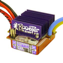
The servos and motors are now fitted. I haven't connected the motors yet but the Novak crawler ESC setup is done.


In fact it does itself, you just connect the battery and switch it on WHILST holding the setting button down. The red LED goes on in under two seconds - release the button and apply full throttle and the green LED comes on - apply full brake and the green one flashes. That's it - done.


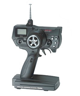
I've found the instructions for setting up the 3PM on a RCCrawler.com Bulletin Board. Here they are - with many thanks to and by courtesy of poster bbeaty:

Setting up Futaba 3PM for 4ws

For 4ws the front wheels turn opposite the rear (the same as if you had a reversing y-harness). When the SW2 button on the radio is moved the truck will steer only with the front (mixing turned off), and when the SW1 button is pressed the front wheels will turn the same as the rear enabling crab steering.

Setup Procedure:

To set this up you will need to have a servo plugged into the CH1 and CH3 positions on the radio. For now I’ll assume you have the front servo plugged into CH1 and the rear servo into CH3.

In the system menu setup a new model name in the radio, also while in the system menu, setup SW2 to be MX (programmable mixing) see pg 54 in manual if you do not know how to do this, and SW1 to Conditions 2 selection (pg 56).

Turn the radio on normally; I assume you know how to setup the front steering using the sub trims and EPA. If you need to reverse the front steering do this as well. In order to have the rear steer opposite from the front, the value for CH3 in the reversing menu needs to be opposite that of the steering. For example, if you need to reverse the front steering CH3 should not be reversed, and by the same measure if the front steering does not need to be reversed then you will need to reverse CH3.

To adjust the mixing settings see (pg 41). For a base value set both the right and left side values to +75. You will need to fine-tune them later using the same idea as setting the steering EPA. The master and slave settings are correct by default and then set PMX-MD to ON.

To test the settings try steering the truck, only the front tires should turn. Now if you move the SW2 switch the truck should steer normally with 4ws.

The rear steering will most likely need to be trimmed. The preferred method to trim the rear wheels is to use the sub trim menu and select CH3, then use the + / - buttons to align the rear wheels. Another method is to select CH3 in the main menu and again use the + / - buttons to align the rear wheels.

Here is where the Conditions 2 button you setup earlier comes into play. The conditions 2 button is setup as SW1 (button on the handgrip). When you press the button you will notice the LED will flash, verifying you are in the Condition 2. Now scroll though the menu and setup the mixing function again, however this time instead of setting the right and left values to +75 set them to –75. Now when you have the SW2 moved to activate mixing and have the SW1 button pressed, the front and rear wheels will turn the same direction and the truck will crab steer.

When mixing is turned off via SW2, you can set if you want only the front or rear wheels to steer by switching how the servos are plugged into the receiver (front on CH3, rear on CH1). Keep in mind when you physically switch the front and rear servos on the receiver you will need to readjust the trims, channel reversing, etc.

I'll try this all out tomorrow. X fingers...

First look (sneak preview)

Who can resist placing their bodyshell onto their truck just as soon as the chassis is done?


(I'll borrow a better camera just as soon as everything is finished!)

Saturday, 18 July 2009

The chassis is complete...


This chassis is now completely assembled. It was a bit of a struggle getting the batteries (which have now been swapped out for 4600mAh packs) into place, being as they squash a fair way into their foam rubber padding. At least they don't require any additional retaining devices like cable ties or similar. The articulation looks good, and nothing contacts anything else where it shouldn't.


One thing that needs a bit of adjustment is the positioning of the cantilever-to-axle rods, being as they cant in different directions due to the fact that the main gearbox is not central to the main longitudinal axis of the truck in the first place. A small spacer with a longer screw on the right hand (as viewed here) side of each axle will do the trick. The plates that mount the rods to the axle stays haven't been painted yet because they are due to get trimmed (being as they are a universal left/right/front/back item). Also, the mounting holes which pre-exist in the axle stays are vastly oversize in the first place, so they need a bit of packing - I've done this before with M3 spring washers as they are the right size - unfortunately I haven't got any here right now. The next thing to do is to mount the new motors (along with their 9T pinions and adjustable motor mounts) and the steering servos.

One thing outstanding is to sort the differentials. I've got plenty of choices here:

1. leave them standard, which is going to help the steering but harm the traction;

2. lock the existing ones with something like JB weld or hot glue, which is going to do the complete reverse;

3. buy a pair of new output gears, which does away with the differentials all together;

or 4. buy Integy ball differentials, which are essentially limited-slip devices (and also the most expensive option).

There are also 5th to 7th options, all of which are to just lock up or semi-lock the rear end alone (by one of the three methods above).

Hmmm. A bit more thought is required!!

Friday, 3 July 2009

Meantime...

My backyard basher truck:


This started out as a child's toy New Bright Motorsports truck. As RC vehicles go, it was pretty poor. It took the whole width of a road to do a 'U' turn, was either going flat-out or was stopped, and had trouble accelerating (read getting going) on 2" long grass. So I improved it (no end). The same shell now resides on a Tamiya TL-01B Baja King chassis. It wears F350 wheels and tyres, has a full compliment of ball-bearings, uses a Futaba MC230CR ESC and carries a 2400 mAh battery. Great fun. I love it to bits.

Wednesday, 1 July 2009

Motor choice

This project is being funded in large part by the sale of unwanted motorcycle parts. I've sold a pair of 1970's Suzuki GT250 fork legs for £39.99 this week, so this was my basic budget for a pair of motors. Suitable 540 size motors for a Clodbuster/Clodzilla project come in a lot a variations with regard to the winding turn count - the stock motors are reported to be either 23 or 27 turns, with lower turn counts giving higher RPM and higher counts giving greater torque at the price of much lower peak RPM. Typical values here (for Team Atlas Rock Climber Motors) are: 40T 11000RPM, 60T 8030RPM, 70T 6700RPM, 80T 5940RPM, 90T 4730RPM and 100T 3850RPM.

Purist rockcrawling motors have turn counts running up to about 110 turns, but this is far too extreme for me, what with the 10 tooth pinions I have bought this would give me a top speed far less than walking pace, maybe as low as 1 1/2 or 2mph.

My design criterion requires motors in the 35-50 turn range (being as my ESC has a rating of anything down to two 35t motors), and the budget was £20 tops for each motor. This narrowed the field down to about four final choices:

Atomic (various turns):


$21.00 each (£12.75) + $16.00 P+P (from San Gabriel, California).

Venom Fireball 50:


£17.99 each + £2.00 P+P (from West Yorkshire).

Integy 45t:


$17.99 (£10.92) each for the V10 version, $33.99 (£20.64) (discounted from $37.99) + $9.84 (£5.96) P+P for the V11 (from Salt Lake City, Utah)

Final choice - Tamiya 35t (54114):


£39.00 + £2.00 P+P each here in the UK; or $23.95 (£14.54) + $7.50 P+P from Hong Kong. (You can guess which I choose!)

The blurb says:

"When rock crawling, it is very important to have a motor that provides the appropriate amount of torque required, to give you more control over the vehicle. Tamiya is releasing the CR-Tuned Motor (35T) to meet the needs of all Rock Crawlers."

"This CR-Tuned Motor (35T) is perfect for rock crawing machines that run at low-speeds and need precise acceleration inputs."

The specifications say:

For: CR-01 Chassis Vehicle, Big Tire Trucks, Touring Cars and M-Chassis Vehicles

MAX RPM is reduced to focus on increased torque.

Features smooth power transfer and long endurance.

Black motor body with an end bell that acts as a heat sink.

0 Degree lead angle for consistent performance.
(Meaning I don't have to reverse the direction of the rear motor to suit the Clodbuster configuration.)

Replaceable standard type brushes.

Turns: 35T

Voltage: 7.2V

RPM when not loaded: 12,000 RPM (7.2V)

Motor Size: 540

Gear Ratio: 32.4~50.6

Max. Torque: 36.7mN-m (7.2V)

I hope they are good. Everything just about stops now for a couple of weeks until they arrive. I may well have a go at making skid plates for the gearboxes and under the centre body in the meantime. Back to the workroom benches we go...

Saturday, 27 June 2009

Motor wiring

I got the motor wiring done this morning. They are in parallel. To change to a series setup I simply have to swap out the connector blocks to three 1-1s, instead of two 2-1s.


A bit of heatshrink and a few cable ties to finish off. I usually wrap things twice with tape before using the ties, this prevents them from chewing up the outer insulation.

Build proper - stage 2

Starting from the back:

This next piccy shows the back axle of the truck. To set the tracking right (well - straight anyway) I've had to add four M3 washers under the cross-rod jamnuts. If you look carefully you can see the top link/axle mount nut is just a squidge on the short side. My fault (partly) cos I put a washer on the other end of the screw. The bottom one works out perfectly as it doesn't need the extra length to go through the axle stay. The short steering rod worked out fine, even though I added an extra locknut on top of the bracket to both clamp the bracket better, and to raise the outer end so as to give it a straighter push/pull.


Moving to the front:

Here I've changed the top link screws for much longer ones, and put two extra M3 plain nuts on each screw, going on before the conical washer. This has had the effect of giving me just a bit more (5/32 or about 4mm) tyre-to-rod clearance. As standard, the tyres just brush the rods at full steering deflection, and now they don't. A future upgrade may well be to put wheel extensions on all four corners, to increase the track width (it seems various sizes are available). At the minute there is no point doing anything to the standard steering stops as the rods limit steering travel in any case.


Top down:

A rubbish pic I know (it's a cheap camera under artificial light) but you can just about see what I'm talking about re the tyre clearances (front at the top of the piccy).


Other bits:

Mostly ready to fit now. The servo mounts have been to the vice and received a radiusing on their bottom edges. A larger radius on one side (towards the centre of the truck) should mean they better match the profile of the gearboxes. Their top surfaces have been wrapped with thick wide plastic tape so that the double-sided tape used (white - as seen on one of them) to help mount the servos themselves won't take the paint off if I come to change it. Tape-to-tape will stick together better too.


And on with the electrics...

This is what I think I'll need. Basically I've got to pair off the batteries to supply the ESC; and then pair off the ECS output to supply both motors. I've got some standard 'Japanese' bullet connectors, which are exactly the same as Tamaya used in the first place, so I don't need to chop the motor connectors off. The other ones are heavy duty automotive 6.3mm female blades, which match the 2-1 male fitting blocks, these are to twin the motor supply. New wire is 16AWG, which is an upgrade on the stock variety, the difference in size is seen by comparing the standard piece (which has connectors on here).

Friday, 26 June 2009

Something I'll probably come back to later...

SHOCKING STUFF!!!

As I mentioned before, I'd had some thoughts about using long-length laydown shocks to suspend the 'Zilla. I've placed them in at this stage just to have a proper look at the geometry. They fit in there quite well, with just a bit of preload to support the weight of the centre chassis and batteries. As I've arranged things they centre up on the radiused area of the stock axle braces. They're mounted at the bottom someway inboard on the top (stock) swivel hub mount hole.


I think to look better in this arrangement the main frame rails need to be shorter, say an inch or so longer (25-30mm)(on each end) than the centre section itself is. There needs to be enough room on the rail ends for the body mounts to fit (as standard), the cross rails need to go next, and then the top shock mounts themselves mount just ahead of centre body assembly.

What I DON'T WANT TO DO at the moment is to cut down my existing frame rails. I want to build the truck as close to stock as possible to begin with, which means using the suggested and supplied cantilever setup, and then to (perhaps) work away from that, using this system as a benchmark to see I'm developing further in either a positive or negative direction.

When I get a chance I'll draw up the new rails on paper (or a screen). I'd have three options to get them made/make them to my specifications, contact Eric at ESP to see if he likes the idea and what he'd charge to have a go at a pair; try scrounging a suitable piece of similarly sized section and then cut and drill it myself; or go and see my mate Martin, who owns a lovely milling machine and sometimes only charges beer money!

Build proper - step 1

OK - here we go with the final build. I've assembled the axles, the lower links and the centre lower section. The holes in this for the links were oversize to begin with (see below) so these were packed out with slices of PVC plastic tubing. One thickness was sufficient in the underside holes, and two (different thicknesses) were required in the lower side holes. I used the conical washers as recommended, and everything screwed down nice and tightly. The heads of the screws gained a washer each, and M3 nylock nuts finished off this part of the assembly.


Packing for the batteries has been made from 1/4 inch closed cell foam, which actually used to be the base of a mouse-mat. Holes were punched to accomodate all the protruding screwheads and washers/nuts, this was done by filing a taper on the end of a handy off-cut piece of stainless tube and just pressing through by hand against a wooden block.


The batteries were taped together to form a '^' shape. For the time being they will be permanent fixtures in the truck, rather than being removable for charging. These ones are only 1900mAh each, and will be upgraded to about twice this capacity later (when funds allow).


The electrickery comes next. This is going to be easier with the chassis partly assembled, as it is now. Wire lengths need to be sorted, and I want to try an arrangement whereby both motor series and parallel wiring can be arranged to suit running conditions. (The plastic twin wall mount for the Tx and ESC can be better seen in this shot.)

Thursday, 25 June 2009

Prime and Paint

'Zilla's gonna be black!

Key:


First-up everything got a good keying with a #400 grit sanding block. Aluminium is notoriously hard to get paint to stick to so this step is essential. Everything was then cleaned/degreased using cheepy (£1 a can) choke and carb cleaner.

Prime:


Priming was done with 1K etch primer, which actually bonds with the substrate material. Two coats on everything.

Paint:


Holts acrylic satin black goes on next. I usually try to get 4 coats on in all, starting with two very light ones with a fair-old buildup on the last. I messed up here because the long rails stuck to the paper, and one top sideplate flipped over as I tried to move it. Basically the choices are do it on paper, which minimises the amount of overspray getting into the atmosphere, or hang them up. I opted for the first, and as long as you move things about quite rapidly before the paint dries you can usually get away with it. Last thick coats are the worst to do. Never mind. The insides of the rails got plenty. Problem is I ran out of satin, now I've only got matt. Oh well - mix and match!

Monday, 22 June 2009

Shocks on

The shock absorbers are now here. 95 mm long and oil filled. £9.99 for four:


Also arrived - a set of Hot Racing 9T pinions and adjustable motor mounts: